Thursday, October 27, 2011

Persistence of Vision

Our eyes have a property of persistence of vision. It means that an after-image persists even after the original image no longer exists. This after-image persists for approximately 1/25 th of a second.
So let's say, there are some red LED. The LED blink one after another with a gap of, say, 1 second. In this case I will be able to notice a change in the state of the LED, that is whether it is ON or OFF, as shown in the video below:


Now, say I reduce this time gap to about 500 milliseconds. This is what will happen:


If I further reduce the time gap, this is what it will look like:


In the next video the time gap is of the order of micro-seconds.

So, you see, in each of the above cases, I was turning ON only one LED at a time, but as the time delay between turning ON and turning OFF reduced, all the LED seemed to be ON at a time, forming the smiley figure in the last video.
This method is used in all LED displays you might have seen, on the buses, or the railway station..etc.

Instead of the 8x8 LED matrix used above, we could also use a row of LED. 
--> For a single row of LED

Look at the diagram below. 
t1, t2..t7 have units of time. So, at each t1,t2 etc, the state of the LED will change.


Now, to display a smiley face:


Thus, at time t1, display nothing. Then at t2,t3,t4,t5,t6 display as shown in the picture.
For example, the code for the smiley face will be:

#include<avr/io.h>
#include<util/delay.h>
void main()
{  DDRC=0xff;   // making PortC as output port
   while(1)
  {  
     PORTC=0x00;   // at t1;
    _delay_us(10);

    PORTC=0b00001000;  // at t2  , note that the last row in PC7 and the first row in PC0
    _delay_us(10);

    PORTC=0b00010010;  // at t3
   _delay_us(10);
  
   PORTC=0b00010000;  // at t4
   _delay_us(10);
  
   PORTC=0b00010010;  // at t5
   _delay_us(10);

   PORTC=0b00001000;  // at t6
    _delay_us(10);

  PORTC=0x00;   // at t7
  _delay_us(10);
  }
}
// we can ignore t8 here as it is not required. t7 was included to 
//make sure that there was sufficient space between smileys.

Now, all we need to do is move it at a high speed. Since, I couldn't find a cheap enough high rpm motor. I stuck the circuit up on my fan, the result was this :

Circuit board on the fan

Smile!!
Yeah, I know, the characters look a little stretched. To correct that you'll have to adjust the delay period.

One more pic:

The characters appear to be reversed because I did not take into account the direction of rotation of the fan.


Follow Techila on facebook.

So, until next time.. Sayōnara!

Wednesday, October 19, 2011

A Robotic Arm


I wrote just the code for controlling this robot. The mechanical structure isn't mine. It had 3 degrees of motion. The robot was already assembled. The controlling chip was an ATMega16. A Potentiometre was used to sense the movement of the arm, potentiometers were used. One was used to indicate movement of the finger, other for sensing the movement of the wrist and the last one to check for the movement of the elbow.
In this video we are simply rotating the potentiometer to control the arm. Watch how it almost falls over.


Visit us on Facebook.
Bbye! :)

Saturday, October 8, 2011

Making a Microcontroller Circuit on a Veroboard

Most competitions do not allow use of development boards. In these cases you need to make your own circuit on a veraboard or a breadboard. A veraboard is a much suitable option.


In this post we will be making a basic circuit for an AVR Micro-controller without any peripherals.


Items you will need:


1) Veroboard
Top side of the Veroboard. Soldering is done on the bottom side.


2) IC Holder 
40 Pin IC Base for ATMega16


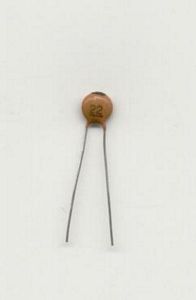
3) 2 Capacitors- 22pF each


4) 1 Capacitor- 100nF


5) A crystal to function as an external clock. Several are available, I used a 16 
    MegaHz crystal.


6) A voltage regulator IC 7805


7) The most important of them all, a Microcontroller (ATMega16 used here)


Now, pins like XTAL1, XTAL2, AREF, AVCC, GND, VCC, RESET are common to all microcontrollers. They may be present with a slightly different name in some, but are present in all.


Consider the pin diagram of an ATMega16


  • The crystal is connected at Pin number 12 and 13, i.e XTAL2 and XTAL13. Connect one end (any) of the crystal at Pin 12 and the other at Pin 13
  • Pin number 32 (AREF) is connected to a 100nF capacitor which is then connected to ground.
  • Pin 10 (VCC) and pin 30 (AVCC) are shorted. Pin 10 (VCC) is connected to a 5 Volt supply.
  • Pin 31 (GND) and Pin 11 (GND) are shorted and connected to ground.
  • A Voltage Regulator IC LM7805 is used. The positive terminal of the battery is connected to input of 7805, the negative is connected to middle pin of 7805 and the 3rd pin gives regulated output of 5 V for input voltage greater that 7.5 Volt.


Now, get the Veroboard out. The side shown in the picture in the beginning is the top side. No soldering is done on this side. Soldering is done below it.

First, on a rough sheet make a plan of the circuit you want to make.

Next, place the IC base at an appropriate position. If you are connecting some other components like IR LED, buzzer etc. on both sides of the Microcontroller, it is best to place the IC base in the middle. If, let's say the peripheral components are to be connected only on the right side, place your IC base on the extreme left of the veroboard, giving just enough space to place and connect a capacitor.

Once the IC base position has been decided, short (connect) Pin 10 (VCC) and Pin 30 (AVCC).
Then, short (connect) Pin 11 (GND) and Pin 31 (GND).
Make sure that the VCC and GND pins do not come in contact with each other!


Next, place the crystal and connect one of it's legs to XTAL2 and the other to XTAL1.

Then, to each leg of the crystal connect a 22pF capacitor and ground the other end of the capacitor.

Place the LM7805 IC on the veroboard.
Note: With the flat side facing away from you, it's I-G-O, i.e Input-Ground-Output


Connect the +ve terminal of the battery or the power-supply to Input pin of LM7805.
Connect the GND pin of LM7805 to the GND of the battery or the power-source.
This GND is also connected to Pin 31 and Pin 11 of the Microcontroller.
Also note, all the GND points on the circuit should be linked to each other which is finally connected to the GND (or the -ve) of the power-supply.

Connect the output pin of LM7805 to Pin 10 and Pin 30. This pin gives the 5V output supply.

The circuit will finally look like this:


Adios until next time! :)

Tuesday, October 4, 2011

Image Processing (Acquisition)

 In this post we will talk about Image Acquisition and processing using Matlab.

A digital image is composed of 'pixels' which can be thought of as small dots on the screen. A typical size of an image is 512-by-512 pixels. Later on in the course you will see that it is convenient to let the dimensions of the image to be a power of 2. For example, 29=512. In the general case we say that an image is of size m-by-n if it is composed of m pixels in the vertical direction and n pixels in the horizontal direction.

Matlab has an Image Acquisition Tool Box which can be used for acquiring 
images.

To open the toolbox, click on start -->


Toolboxes ---> Image Acquisition ---> Image Acquisition Tool (imaqtool)

Once the Image Acquisition ToolBox is open, you could start preview, view the type of camera you are using etc.

You could also do all this using MATLAB commands.

Plug in a camera to your laptop.
In the Workspace, type:
imaqhwinfo
and hit enter.

You will get an output something like this:


>> imaqhwinfo

ans = 

    InstalledAdaptors: {'coreco'  'winvideo'}
        MATLABVersion: '7.6 (R2008a)'
          ToolboxName: 'Image Acquisition Toolbox'
       ToolboxVersion: '3.1 (R2008a)'

Thus by using this command we can know the adapters installed. 

Now, we want to capture the video, right?
There is a command in MATLAB called 'videoinput'. It helps you to create video input objects. 
Syntax:


OBJ = VIDEOINPUT(ADAPTORNAME)
OBJ = VIDEOINPUT(ADAPTORNAME,DEVICEID)
OBJ = VIDEOINPUT(ADAPTORNAME,DEVICEID,FORMAT)
OBJ = VIDEOINPUT(ADAPTORNAME,DEVICEID,FORMAT,P1,V1,...)

We already got the adapter name by using the imaqhwinfo command. Winvideo and Coreco are the name of the installed adapters. Any one of them can be used.
For format, open the Image Acquisition Toolbox, it will be mentioned on the left side of the toolbox. The camera I was using was a 'YUY2_352x288'. 
In the workspace again type imaqhwinfo(write name of your adapter here) and hit enter, this will give you the device id.


>> imaqhwinfo('winvideo')

ans = 

       AdaptorDllName: 'C:\Program Files\MATLAB\R2008a\toolbox\imaq\imaqadaptors\win32\mwwinvideoimaq.dll'
    AdaptorDllVersion: '3.1 (R2008a)'
          AdaptorName: 'winvideo'
            DeviceIDs: {1x0 cell}
           DeviceInfo: [1x0 struct]

Thus, the device id is 1.

So, my videoinput statement becomes something like this:

obj=videoinput('winvideo',1,'YUY2_352x288');

Next --> triggerconfig
This command is used to configure the trigger settings of the video input object. i.e it defines how you want the camera to trigger, whether it should be  manual or auto.
We define it manual because we want it to start only when we need it.
remember that 'obj' is the video input object we have defined.

thus, my command statement looks like this:
triggerconfig(obj,'manual');

Now, we need to set the number of frames we want the camera to capture every time it's triggered. For my use i set it to 1. Also, the triggering should happen continuously, thus it should also be set to infinity.

set(obj,'FramesPerTrigger',1);
set(obj,'TriggerRepeat',inf);


after that start(obj) initializes 'obj' which is the object defined for videoinpout. 

If you want to preview the video during run-time, give the command preview(obj) after start(obj).

Thus our code in MATLAB till now is:


obj=videoinput('winvideo',1,'YUY2_352x288');
triggerconfig(obj,'manual');
set(obj,'FramesPerTrigger',1);
set(obj,'TriggerRepeat',inf);
start(obj);
preview(obj);

To trigger the camera the command: trigger(obj), is used.
use the getdata command to get data and store it in a variable
im=getdata(obj,1);

Thus, now we have one image stored in im.

I recently took part in a competition in which I had to follow a red line by using a web-cam to see the line.
In such a case, the image that was obtained contained a red line on a white background. The preview window (which you get by using the preview(obj) command) looks like this :


This image needs to be converted into grayscale image first. A grayscale image represents an image as a matrix where every element has a value corresponding to how bright/dark the pixel at the corresponding position should be colored. 
the command rgb2gray is used to conver the image to grayscale.
The camptured image is stored in im.
thus,
b=rgb2gray(im);
Now, b stores the grayscale image.
Below are shown two grayscale images with index intensity values for the RED portion and the WHITE area.


Thus we see that there is a difference between the index values of WHITE and RED.
A function roicolor() can be used to definitely separate red and white by specifying a range of threshold index value. All values within that range will show as white and values outside that range will show as black. 

a=roicolor(b,[100,115]);


 The black portion in between the white strip where the red tape was is because of there was a high intensity reflection of the room light (see in preview image above)

Now we invert the image, i.e make the black region white and white region black, so that the region of interest shows up more clearly.


Now that we have this image, we calculate the centre of gravity of the black portion of the image. If the centre of gravity lies near the centre of the image, we send instruction to our robot to keep moving forward, else the centre of gravity lies somewhere on the right side, the bot should move right and similarly for moving left side. The range of centre of gravity needs to be decided by us. For my use, I specified that if the x coordinate of the centre of gravity was between 140 and 180 the robot should move straight, if it was above that the robot should move right else left.

The instructions were sent to the microcontroller using UART communication.
The serial port can be configured in MATLAB using these commands:

ser= serial('COM42','BaudRate',9600,'DataBits',8); 
fopen(ser); 

The command fwrite(ser,'character') can be used to transmit data using UART.

At the end of the code, the serial port has to be closed and the videoinput object closed. My final code looked like this:


clc;
clear all;
close all;
obj=videoinput('winvideo',1,'YUY2_352x288');
triggerconfig(obj,'manual');
set(obj,'FramesPerTrigger',1);
set(obj,'TriggerRepeat',inf);
start(obj);
ser= serial('COM42','BaudRate',9600,'DataBits',8); 
fopen(ser); 
while(1)        % infinite loop

    trigger(obj); 
    im=getdata(obj,1);   %get the image

    trigger(obj); 
    im1=getdata(obj,1);  % the first time triggering occurs the image is just
                                  % noise. Thus the 2nd image is used.
    b=rgb2gray(im1);      % convert to grayscale
    a=roicolor(b,[100:118]);  %define a region of interest
    a=~a;
   
    c=center(a);
                      % use disp(c) to see the values, while testing
    if (c(2)>190)
    fwrite(ser,'r');  % send move right
    elseif (c(2)<170 && c(2)>10)
    fwrite(ser,'l');
    elseif c(2)<170
    fwrite(ser,'l'); % stop

 end
 end
 fclose(ser);
stop(obj),delete(obj),clear obj;  
-------

The function center(a) that I have used is not an inbuilt function. I would suggest you attempt to write it on your own.

This is the video of the robot following the red line.