Most competitions do not allow use of development boards. In these cases you need to make your own circuit on a veraboard or a breadboard. A veraboard is a much suitable option.
In this post we will be making a basic circuit for an AVR Micro-controller without any peripherals.
Items you will need:
1) Veroboard
2) IC Holder
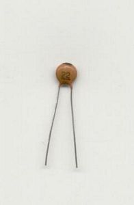
3) 2 Capacitors- 22pF each
4) 1 Capacitor- 100nF

5) A crystal to function as an external clock. Several are available, I used a 16
MegaHz crystal.


6) A voltage regulator IC 7805

7) The most important of them all, a Microcontroller (ATMega16 used here)

Now, pins like XTAL1, XTAL2, AREF, AVCC, GND, VCC, RESET are common to all microcontrollers. They may be present with a slightly different name in some, but are present in all.
Consider the pin diagram of an ATMega16


In this post we will be making a basic circuit for an AVR Micro-controller without any peripherals.
Items you will need:
1) Veroboard
 |
| Top side of the Veroboard. Soldering is done on the bottom side. |
2) IC Holder
 |
| 40 Pin IC Base for ATMega16 |
3) 2 Capacitors- 22pF each
4) 1 Capacitor- 100nF
5) A crystal to function as an external clock. Several are available, I used a 16
MegaHz crystal.


6) A voltage regulator IC 7805
7) The most important of them all, a Microcontroller (ATMega16 used here)
Now, pins like XTAL1, XTAL2, AREF, AVCC, GND, VCC, RESET are common to all microcontrollers. They may be present with a slightly different name in some, but are present in all.
Consider the pin diagram of an ATMega16
- The crystal is connected at Pin number 12 and 13, i.e XTAL2 and XTAL13. Connect one end (any) of the crystal at Pin 12 and the other at Pin 13
- Pin number 32 (AREF) is connected to a 100nF capacitor which is then connected to ground.
- Pin 10 (VCC) and pin 30 (AVCC) are shorted. Pin 10 (VCC) is connected to a 5 Volt supply.
- Pin 31 (GND) and Pin 11 (GND) are shorted and connected to ground.
- A Voltage Regulator IC LM7805 is used. The positive terminal of the battery is connected to input of 7805, the negative is connected to middle pin of 7805 and the 3rd pin gives regulated output of 5 V for input voltage greater that 7.5 Volt.
Now, get the Veroboard out. The side shown in the picture in the beginning is the top side. No soldering is done on this side. Soldering is done below it.
First, on a rough sheet make a plan of the circuit you want to make.
Next, place the IC base at an appropriate position. If you are connecting some other components like IR LED, buzzer etc. on both sides of the Microcontroller, it is best to place the IC base in the middle. If, let's say the peripheral components are to be connected only on the right side, place your IC base on the extreme left of the veroboard, giving just enough space to place and connect a capacitor.
Once the IC base position has been decided, short (connect) Pin 10 (VCC) and Pin 30 (AVCC).
Then, short (connect) Pin 11 (GND) and Pin 31 (GND).
Make sure that the VCC and GND pins do not come in contact with each other!
Next, place the crystal and connect one of it's legs to XTAL2 and the other to XTAL1.
Then, to each leg of the crystal connect a 22pF capacitor and ground the other end of the capacitor.
Place the LM7805 IC on the veroboard.
Note: With the flat side facing away from you, it's I-G-O, i.e Input-Ground-Output
Connect the +ve terminal of the battery or the power-supply to Input pin of LM7805.
Connect the GND pin of LM7805 to the GND of the battery or the power-source.
This GND is also connected to Pin 31 and Pin 11 of the Microcontroller.
Also note, all the GND points on the circuit should be linked to each other which is finally connected to the GND (or the -ve) of the power-supply.
Connect the output pin of LM7805 to Pin 10 and Pin 30. This pin gives the 5V output supply.
The circuit will finally look like this:

Adios until next time! :)
No comments:
Post a Comment